Burns & McDonnell, an international engineering, architecture, and consulting firm based in Kansas City, Missouri, released a new project profile featuring the state-of-the-art fuel storage facility at Point Loma, CA. A copy of the TechBrief can be viewed below.
REFUELING THE LIFESPAN
Effective Secondary Containment System for the State-of-the-Art Fuel Storage Facility at Point Loma
By Hassan Sahudin, PE, LEED AP BD+C; Bill Shehane, Seaman Corp., and Alan Strecker, Seaman Corp.
In 2008, an eight-year military construction project (MILCON P-401) was approved to replace the aging Point Loma Navy fuel storage facility originally constructed between 1917 and 1954. Located at Defense Fuel Support Point (DFSP) Point Loma, San Diego, this was the largest construction project ever within the Defense Logistics Agency Energy (DLA Energy) at $174 million. Eight 125,000-barrel aboveground fuel storage tanks were constructed to replace the existing 1 million barrel capacity of jet and diesel fuel storage. A fuel-resistant reinforced polyurethane geomembrane liner was used under each tank and a fuel-resistant reinforced ethylene interpolymer alloy (EIA) geomembrane was used in the dike areas for secondary containment. The project was contracted through NAVFAC Southwest, and Burns & McDonnell provided engineering services. Design began in March 2005 with construction closeout in January 2014.
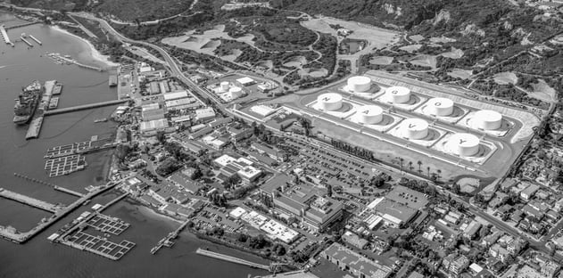
Image 1: Burns & McDonnell helped upgrade the Point Loma Navy fuel storage facility with eight 125,000-barrel aboveground fuel storage tanks.
PROJECT GOALS
In addition to the U.S. Navy fleet, DFSP Point Loma services a number of other agencies including the U.S. Marine Corps Air Station Miramar, the 11th District of the US Coast Guard/Homeland Security, the National Oceanographic and Atmospheric Administration (NOAA), and Military Sealift Command (MSC). The project upgrades were necessary to modernize existing fuel storage infrastructure with 21st century operation requirements in mind and to maximize sustainable practices. In addition, the project sought accreditation from the U.S. Green Building Council (USGBC) for Leadership in Energy and Environmental Design® (LEED) status.
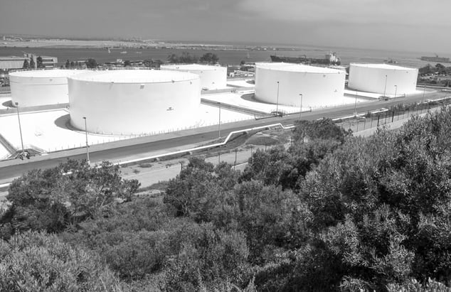
Image 2: Using white tanks and liner help reduce the heat island effect at Point Loma.
EXISTING CONDITIONS
The Point Loma facility was originally constructed in 1901 as a storage point for Navy coal. Since operations first began, the facility has modified and expanded its infrastructure to accommodate petroleum-based fuels and increase use by air and sea forces. Tanks were added over the years for storage. Before this project was constructed, the site included 54 storage tanks, the last of which were added in 1954. Both aboveground storage tanks (ASTs) and underground storage tanks (USTs) provided storage for approximately 1 million barrels, or 42 million gallons. The location increased its service to provide more than 460 million gallons of fuel and oil to the many commands it served by 2003. Most of the original tanks, constructed with riveted seams, were leaking at various rates. As a result, the DFSP command actively extracted fuel and contaminated water from site soils. Replacing the tanks was necessary
to prevent further contamination and fuel loss.
CONSTRUCTION
Initial construction included the demolition, or closure in place, of all existing ASTs and USTs and removal of containment berms. Old material and equipment were used to the extent possible. Located on a hillside, the site underwent major grading modifications to better accommodate the new facility and redirect stormwater, including the construction of new stormwater basins. The site soils were remediated to remove fuel and oil contaminants. Where possible, existing vegetation was left in place and porous surfacing material, such as crushed aggregate, already on site was used as ground cover. Eight new ASTs were installed during construction, each with a storage capacity of 125,000 barrels (Image 2), which primarily store jet fuel (JP-5) and marine diesel fuels (F-76). Other major new structures included a pumphouse, a truck load/unload facility, a lube oil storage and transfer facility, a fuel oil recovery (FOR) facility, which included a 25,000-bbl AST receipt tank and a 10,000-bbl issue tank, and a two-story control tower near the existing fueling pier.
SECONDARY CONTAINMENT
With demolition of the existing earthen embankments, new containment structures were needed. Exposed concrete vertical dike walls were used for perimeter enclosure, and flexible membrane liners (FMLs) were selected in lieu of concrete floor for use as secondary containment. FMLs offer a number of advantages over concrete in this application.
Lower cost. Typical concrete containments cost $6-$7 per square foot installed (Bausch 2013). FML installed costs are typically $1-$2 per square foot.
Rapid installation. FML containment on nearly 12 acres was installed in less than 25% of the time required for concrete floors.
Reduced maintenance. FMLs do not require a sealant along the joints/seams to be applied or maintained as concrete does. Repair of FMLs is a simple, inexpensive process that can be done with patches applied by hot air welding or adhesives.
Under Tank Secondary Containment
Guidance for the design of secondary containment under fuel storage tanks is provided in UFC 3-460-01. Product selection direction is given in the Naval Facilities Engineering Command’s (NAVFAC) Unified Facilities Guidance Specification (UFGS) Section 33 56 13 15. The UFGS guidelines call for reinforced thermoplastic urethane (rTPU) underneath because of its superior long-term resistance to chemicals, construction damage, a broad range of fuels and oils, and gasoline and volatile organic compounds. The superior abrasion and puncture resistance of rTPUs increases the likelihood that the liner won’t be compromised during construction. More than 142,000 square feet of rTPU, manufactured by Seaman Corp., was used on this project.
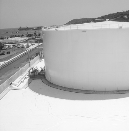
Image 3: Using a white membrane liner system provides effective secondary containment in the dike areas.
Dike Secondary Containment
A scrim reinforced FML — in this case, a coated knitted polyester — was chosen for the containment liner in the dike enclosed area. The coating chosen was ethylene interpolymer alloy (EIA), which is an alloy of PVC, and a ketone ethylene ester (KEE), Elvaloy. A DuPont product, Elvaloy differs from traditional plasticizers in two significant ways. First, KEE is solid rather than liquid. Second, it is an extremely large molecule. While traditional liquid plasticizers have molecular weights in the 1,000 g/mol to 5,000 g/mol range, KEEs have molecular weights ranging from 250,000 g/mol to 400,000 g/mol. This is
large even in comparison to PVC molecules which range in size from 50,000 g/mol to 150,000 g/mol. The solid, dense KEE molecules are stable in the coating which has excellent resistance to chemical and UV action. This results in long-lasting performance of the finished EIA FML.
EIA liners have been used in exposed applications for more than 30 years of continuous service. EIAs have been used for secondary containment on more than 50 U.S. military installations. Traditionally, black liner was used. In recent years the trend has moved toward lighter colors to reduce surface temperature on the liner and tan has become a more common color. In same-site comparison tests, the temperature on the surface of black FMLs has been measured at 160 degrees F whereas the white liner adjacent to it has been measured at 130 degrees F. As a side benefit, light-colored liner is easier to clean, inspect and
repair as well.
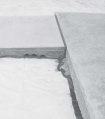
Image 4: Geotextile fabrics placed under concrete sidewalks protect the liner.
Because achieving LEED certification was a goal at the Point Loma facility, the decision was made to use a white liner (Image 5), which resulted in lowering the Solar Reflectance Index (SRI) of the liner to below 29 degrees F. This is the maximum allowed by the LEED “Heat Island Effect, Non-Roof” credit requirement.
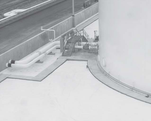
Image 5: The secondary containment area around storage tanks includes vertical concrete dike walls and membrane liner.
In addition to being UV resistant, an EIA provided the advantage of having a low coefficient of thermal expansion. This reduces the probability of liner failure due to environmental stress cracking caused by repeated expansion and contraction. It also meant that maintenance personnel would be able to access the facilities without the trip hazard posed by extreme wrinkling that can occur in geomembranes subject to thermal expansion.
The ability to leave the liner exposed resulted in additional savings in surfacing material and placement costs. In the event of a spill, the containment area would also be easier to clean up without having to remove and remediate the contaminated surfacing materials.
Guidance for the design of secondary containment in dike liner areas is also provided in UFC 3-460-01. Product selection direction is given in the UFGS Section 33 56 63.
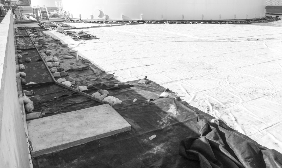
Image 6: Because of potential damage to the liner, traditional steel reinforcing bars and steel from stakes could not be used during construction of concrete sidewalk in the diked containment area.
Access for Personnel
Concrete sidewalks were used to provide access for operations personnel (Images 5 and 6).
Burns & McDonnell used the Corps of Engineers’ standard detail to construct the sidewalks. Because of potential damage to the geomembrane, a geotextile is placed on top of the liner (i.e., below the concrete). Rebar is eliminated from the construction by using fiber reinforcement instead (Image 6). The use of
sidewalks provides safer access for operations personnel and also helps to minimize potential
damage to the liner during operations.
CONCLUSION
The project received a final LEED Silver certification in June 2014. The thermal profile created by the white geomembrane proved to be an important contributing factor. In addition to contributing to LEED achievement, the white geomembrane liner also provided the following benefits:
- Cost-effective secondary containment system
- Ease of maintenance, inspection and repair
- Improved working environment in summer months due to reduced heat gain.
- Proven long-term performance
- Rapid installation
- Reduced thermal contraction and expansion
AUTHORS
 |
 |
 |
| Bill Shehane is the geomembrane market manager for Seaman Corp. He earned his bachelor’s degree in civil engineering from North Carolina State University. | Alan Strecker is the Western geomembrane specialist for Seaman Corp. He earned his bachelor’s degree in chemistry from the University of Colorado Boulder. | Hassan Sahudin, PE, LEED AP BD+C,is a structural engineer at Burns & McDonnell and specializes in the structural design of aviation, industrial and military fueling facilities. He earned his bachelor’s degree in civil engineering and master’s in structural engineering from the University of Missouri. |
REFERENCES
- SS Credit 7.1: Heat Island Effect, Non-Roof, LEED 2009 for New Construction and Major Renovations, USGBC, Washington, D.C.
- Section 33 56 13.15, Undertank Interstitial Space, United Facilities Guide Specifications, NAVFAC
- Section 33 56 63, Fuel Impermeable Liner System, United Facilities Guide Specifications, USACE
To download the original tech brief (pdf), click here.
To view additional white papers and case studies, please visit www.xr-technology.com.


